L – R Series Circuit
A circuit that contains a pure resistance R ohms connected in series with a coil having pure inductance of L (Henry) is known as L – R Series Circuit. When an AC supply voltage V is applied the current, I flows in the circuit. IR and IL will be the current flowing in the resistor and inductor respectively, but the amount of current flowing through both the elements will be same as they are connected in series with each other. The circuit diagram of RL Series Circuit is shown below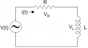 Let VR and VL be the voltage drop across resistor and inductor. Applying Kirchhoff voltage law (i.e sum of voltage drop must be equal to apply voltage) to this circuit we get, V = VR + VL.
Phasor Diagram for L – R Circuit: Before drawing the Phasor diagram of series L – R Circuit, one should know the relationship between the voltage and current in case of resistor and inductor.
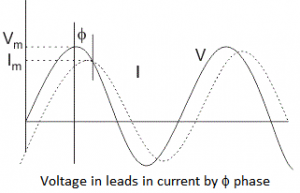
1. Resistor: In case of resistor, the voltage and the current are in same phase or we can say that the phase angle difference between voltage and current is zero.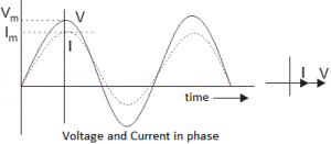 2. Inductor: In inductor, the voltage and the current are not in phase. The voltage leads that of current by 90⁰ or in other words, voltage attains its maximum and zero value 90⁰ before the current attains it.
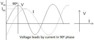 3. L – R Circuit: For drawing the Phasor diagram of series L – R Circuit, follow the following steps:
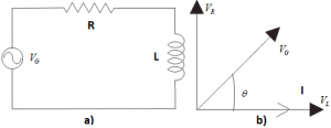
Step – 1: In case of series L – R Circuit, resistor and inductor are connected in series, so current flowing in both the elements are same i.e. IR = IL = I. So, take current Phasor as reference and draw it on horizontal axis as shown in diagram.
Step – 2: In case of resistor, both voltage and current are in same phase. So, draw the voltage Phasor, VR in phase with I.
Step – 3: We know that in inductor, voltage leads current by 90⁰. So, draw VL (Voltage drop across inductor) perpendicular to current Phasor.
Step – 4: Now we have two voltage VR and VL. Draw the resultant vector (VG) of these two voltages. Such as, VR² + VL² = VG² and from right angle triangle we get, phase angle \(\theta =\,{{\tan }^{-1}}\,\left( \frac{{{V}_{L}}}{{{V}_{R}}} \right)\).
 In case of pure resistive circuit, the phase angle between voltage and current is zero and in case of pure inductive circuit, phase angle is 90⁰ but when we combine both resistance and inductor, the phase angle of a series L – R circuit is between 00 to 90⁰.