Half – Wave Rectifier
A rectifier is a circuit which converts the Alternating Current (AC) input power into a Direct Current (DC) output power. The input power supply may be either a single-phase or a multi-phase supply with the simplest of all the rectifier circuits being that of the Half Wave Rectifier.
A half-wave rectifier is a circuit that allows only one half-cycle of the AC voltage waveform to be applied to the load, resulting in one non-alternating polarity across it.
Half Wave Rectification: The power diode in a half wave rectifier circuit passes just one half of each complete sine wave of the AC supply in order to convert it into a DC supply. Then this type of circuit is called a “half-wave” rectifier because it passes only half of the incoming AC power supply.
Half – Wave Rectifier Circuit: During each “positive” half cycle of the AC sine wave, the diode is forward biased as the anode is positive with respect to the cathode resulting in current flowing through the diode.
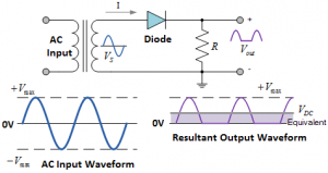
Since the DC load is resistive (resistor, R), the current flowing in the load resistor is therefore proportional to the voltage (Ohm´s Law), and the voltage across the load resistor will therefore be the same as the supply voltage, Vs (minus Vf), that is the “DC” voltage across the load is sinusoidal for the first half cycle only so Vout = Vs.
During each “negative” half cycle of the AC sinusoidal input waveform, the diode is reverse biased as the anode is negative with respect to the cathode. Therefore, NO current flows through the diode or circuit. Then in the negative half cycle of the supply, no current flows in the load resistor as no voltage appears across it so therefore, Vout = 0.