Special Purpose p – n Junction Diode
Zener Diode:
⇒ It is a special purpose diode named after the inventor C.
⇒ It is designed to operate under reverse bias in the breakdown region.
⇒ The symbol for Zener diode is:

⇒ Fabrication – It has heavily doped p – side and n – side. Due to this, the depletion region formed is very thin about < 10⁻⁶. Hence, the field at the junction is extremely high about -5 * 10⁶ V/m for a small reverse bias voltage of 5 Volts.
⇒ The high electric field strength is high enough to pull the valence electrons from the host atoms on the p – side which is accelerated to the n – side. This is known as ionisation.
⇒ Characteristics – The Current – Voltage characteristics of Zener diode is shown below.
⇒ As seen from the graph when the applied reverse bias voltage in Zener diode reaches the breakdown voltage Vz of the Zener diode, there is a large change in current.
⇒ The Zener voltage remains constant even though the current through the diode varies over wide range. This property of Zener diode is used for regulating the supply voltages so that they are constant.
Zener Diode as a Voltage Regulator: We know that the rectifier converts AC current into DC current. When the AC input voltage of a rectifier fluctuates the rectified output also fluctuates. Hence, to get a constant DC voltage from the DC unregulated output of the rectifier we use Zener diode.
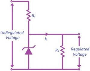
Circuit Diagram:
⇒ The unregulated DC voltage from the output of the rectifier is connected to the Zener diode through a series resistance Rs such that the Zener diode is reverse biased.
⇒ The output is measured across the load resistance RL.
Working:
Case 1:
⇒ When the input voltage increases, the current through Rs and Zener diode increases.
⇒ This increases the voltage drop across Rs without any change in voltage across the Zener diode.
⇒ This is because in the breakdown region the Zener voltage remains constant even though the current in the Zener diode changes.
Case 2:
⇒ Similarly, when the input voltage decreases, the current through Rs and hence Zener diode decreases.
⇒ The voltage drop across Rs decreases without any change in the voltage across the Zener diode.
⇒ Thus the increase or decrease in the input voltage results in increase or decrease of voltage drop across Rs without any change in voltage across the Zener diode. This way Zener diode behaves as a voltage regulator.
Precautions:
⇒ The Zener diode must be reverse – biased.
⇒ The Zener diode must have voltage greater than Zener break down voltage Vz.
⇒ The Zener diode is to be used in a circuit where the current is less than the maximum Zener current Iz limited by power rating of the given Zener diode.