Voltage and Current Dividers
Voltage Divider: A voltage divider is a simple circuit which turns a large voltage into a smaller one. Using just two series resistors and an input voltage, we can create an output voltage that is a fraction of the input. Voltage dividers are one of the most fundamental circuits in electronics.
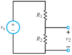
It is interesting and useful to consider how voltage is divided among resistors in series. Consider the circuit to the right. There is only one current flowing around the loop (is).
We know that:
v₂ = R₂is … (a)
We also know that:
is = vs/Req … (1)
Req = R₁ + R₂ … (2)
After substituting equations (1) and (2) in equation (a) we get:
v₂ = R₂/(R₁ + R₂)vs
This is the basic voltage divider result. Namely, the voltage across a resistor in series with other resistors is the ratio of that resistor to the total resistance of all resistors, multiplied by the total voltage across all the resistors.
Current Divider: In electronics, a current divider is a simple linear circuit that produces an output current that is a fraction of its input current. Current division refers to the splitting of current between the branches of the divider.
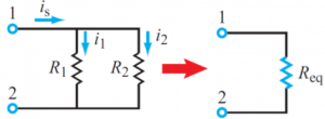
It is equally useful to consider how current divides across parallel resistors.
We know that:
Req = R₁R₂/(R₁ + R₂)
v₁₂ = is Req
Applying Ohm’s law to each resistor:
i₁ = v₁₂/R₁ = (Req/R1)is = (R₂/[R₁ + R₂])is
i₂ = v₁₂/R₂ = (Req/R₂)is = (R₂/[R₁ + R₂])is
Thus, current entering a set of parallel resistors splits such that more current passes through the less resistive path. Note that if one of these resistors is a short (R = 0), all of the current will pass through that resistor.